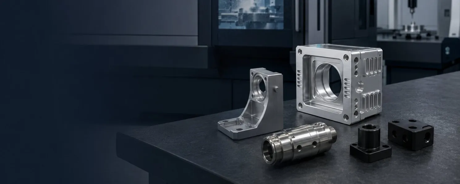
Aug 24, 2026AI Hardware Components
AI Hardware Mechanical Parts Procurement Checklist
A practical checklist covering drawings, tolerances, materials, finishes, and RFQ details for sourcing custom AI hardware components.
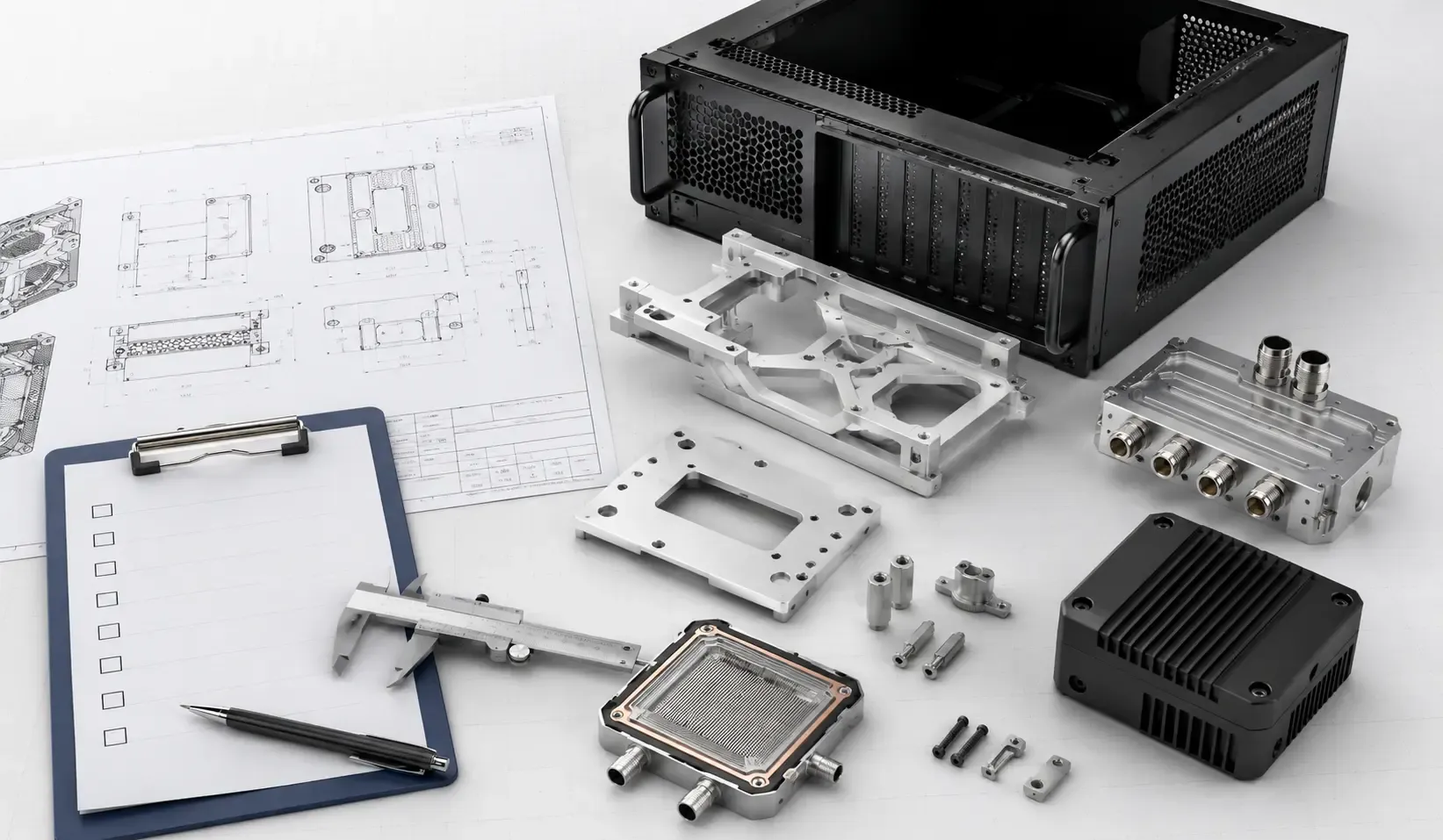
Sourcing custom AI hardware components requires more than sending a 3D model and requesting a price.
AI servers, GPU systems, liquid-cooling equipment and edge computing devices often combine CNC machined parts, sheet metal structures, molded plastic components and purchased hardware within the same assembly.
A complete RFQ package helps the manufacturer understand the functional requirements, select suitable manufacturing processes and identify potential production risks before quotation.
Use this checklist when preparing an RFQ for prototype or production AI hardware mechanical parts.
1. Prepare a Complete Drawing Package
Whenever possible, provide both 3D CAD files and 2D manufacturing drawings.
The 3D model communicates the complete part geometry, while the 2D drawing defines information that may not be clear from the model alone, including tolerances, threads, datums, finishes and inspection requirements.
A useful drawing package may include:
- STEP or STP files for complete part geometry
- DXF or DWG files for sheet metal profiles
- PDF drawings with dimensions and tolerances
- Assembly drawings
- Bill of Materials
- Hardware and fastener specifications
- Drawing revision number and issue date
- Required quantity for each part
Before submitting the RFQ, make sure the filenames, drawing numbers and revision levels are consistent across all documents. If different files show different revisions, the manufacturer may not know which version should be used for quotation and production.
For assemblies involving multiple manufacturing processes, identify which parts require CNC machining, sheet metal fabrication or injection molding, and which items will be purchased separately.
2. Identify Critical Tolerances
Not every dimension requires the same tolerance. Tighter tolerances should be reserved for features that directly affect function, alignment, sealing or assembly.
For custom AI hardware components, critical dimensions may include:
- GPU and motherboard mounting hole locations
- Rack installation features
- Connector and I/O opening positions
- Mating surfaces
- Guide rail spacing
- Cold plate contact surfaces
- Liquid-cooling manifold ports
- O-ring grooves and sealing features
- Camera or sensor mounting positions
- Internal component clearances
Separate these functional requirements from non-critical exterior dimensions. Applying unnecessarily tight tolerances across the entire part can increase manufacturing and inspection costs without improving system performance.
If the drawing uses GD&T, identify the governing drawing standard and edition. ASME Y14.5 provides standardized rules and symbols for communicating geometric requirements.
If general tolerances are applied, state the relevant standard and tolerance class rather than assuming the manufacturer will select one automatically.
Achievable tolerance depends on the material, part size, geometry and manufacturing process. Critical requirements should therefore be evaluated against the actual drawing before quotation.
3. Specify Materials Clearly
Avoid using broad descriptions such as “aluminum,” “steel” or “plastic” without identifying a specific grade.
Material selection can affect strength, weight, machinability, corrosion resistance, electrical insulation, thermal behavior and compatibility with the required surface finish.
Materials commonly considered for AI hardware mechanical parts include:
Component | Material Considerations |
|---|---|
Server chassis and panels | Aluminum, cold-rolled steel, galvanized steel or stainless steel |
GPU brackets and mounting plates | Aluminum or steel, depending on loading and weight requirements |
Liquid-cooling manifolds | Machinable aluminum or other materials specified by the cooling design |
Cold plate components | Materials selected according to thermal, fluid and sealing requirements |
Edge AI enclosures | Aluminum or engineering plastics |
Insulators and spacers | Engineering plastics selected for mechanical and electrical requirements |
Where relevant, specify the complete material grade, condition or temper.
If alternative materials are acceptable, state this clearly in the RFQ and require approval before substitution. This prevents unapproved material changes from affecting fit, function or finishing.
4. Define Surface Finishing Requirements
Surface treatments may be required for corrosion resistance, appearance, wear protection, electrical performance or part identification.
Common options include:
- Anodizing
- Powder coating
- Plating
- Passivation
- Brushing
- Bead blasting
- Painting
- Laser marking
- As-machined finish
The RFQ should specify the finish type, color, texture and any areas that must remain uncoated.
Masking may be required around threads, grounding points, electrical contact surfaces, sealing areas and other functional features. Coating thickness can also affect holes, threads and mating clearances.
If a finished dimension is critical, clarify whether the specified tolerance applies before or after surface treatment.
For cosmetic components, identify the surfaces that will remain visible after assembly. This helps distinguish appearance-critical areas from concealed or non-cosmetic surfaces.
5. Include Assembly and Inspection Requirements
If the supplier will install hardware or assemble multiple components, provide an assembly drawing and Bill of Materials.
Relevant assembly requirements may include:
- PEM nuts, studs and threaded inserts
- Rivets and rivet nuts
- Screws and other fasteners
- Welding
- Adhesives
- Gaskets and sealing components
- Labels and markings
- Cable management hardware
- Purchased components
Inspection requirements should also be defined before quotation.
Depending on the project, inspection may include dimensional measurement, visual examination, thread verification, surface finish checks, assembly verification or agreed inspection records.
Avoid undefined requirements such as “full inspection” without identifying which dimensions must be checked, the expected sampling method and the documentation required.
6. Provide Complete RFQ Information
In addition to the technical drawings, include the commercial information required to prepare the quotation.
RFQ Checklist
- Part name and drawing number
- Current drawing revision
- 2D drawings and 3D CAD files
- Material grade and condition
- Surface finishing requirements
- Critical dimensions and tolerances
- Prototype quantity
- Expected production quantity
- Hardware and assembly requirements
- Inspection requirements
- Packaging requirements
- Required delivery date
- Delivery destination
- Special documentation requirements
If the project is still under development, identify which specifications are preliminary. This allows the manufacturer to distinguish confirmed requirements from details that may change after prototype testing.
Match Each Component to the Right Process
AI hardware assemblies frequently require more than one manufacturing method.
CNC machining may be used for precision brackets, mounting plates, manifolds and enclosure components.
Injection molding may be considered for plastic housings, covers and insulating components intended for repeat production.
Reviewing the complete assembly can help identify interfaces between components and reduce problems caused by tolerance accumulation, incompatible processes or inconsistent drawing revisions.
Submit Your Project for Review
A clear and consistent procurement package supports faster technical evaluation and a more useful quotation.
Before submitting an RFQ, confirm that the drawings, material specifications, tolerances, finishes, quantities and revision levels are consistent.
Upload your CAD files and manufacturing drawings for a DFM review and quotation. We will review the manufacturing requirements and identify details that may require clarification before production.